
Introduction
Have you ever wanted your own cute and friendly musical robot that you can play music with? In this tutorial you are going to build a robot named Dr. Squiggles that is just that. Dr. Squiggles is a musical tapping robot that plays rhythms by tapping on whatever surface you set it on. Moreover, if you tap rhythms, it can listen to you through its microphone, synchronize to your beat, imitate you, or learn to play rhythms that are similar but not identical to what you play. When I designed Dr. Squiggles, I wanted to make the most mechanically simple robot I could think of, and imbue it with the most complex behaviour possible. Functionally, it is just a contact microphone and eight solenoids controlled by an embedded computer. Figure 1
- Eight solenoids that it uses to tap rhythms.
- A low-resolution LED matrix that serves as the the robot's eye.
- A contact microphone that robot uses to listen selectively to rhythms that you play.
- An embedded Raspberry Pi computer, which does the 'smart' tasks of analyzing what you play, and generating rhythms.
- A Teensy microcontroller that animates the eye and receives USB-MIDI messages from the Raspberry Pi. When is receives such a message, it will apply voltage to a solenoid, causing it to eject and make a tapping sound.
- To save cost, it is also possible to build Dr. Squiggles without the Raspberry Pi and contact microphone. You can connect the Teensy to any computer and use your favorite music software or programming language to send MIDI messages that will cause the robot to play. The remainder of this tutorial assumes that you will use a Raspberry Pi and contact microphone.
Materials
Components
| Step | Part | Price (USD) |
|---|---|---|
| 1 | Plywood Sheet, 300 x 400 x 4 mm (3.75 mm measured thickness) | 3.00 |
| 2 | Clear Spray Acrylic | 9.00 |
| 2 | Black Furniture Paint | 11.00 |
| 2 | Glitter | 4.50 |
| 3 | Teensy 3.2 | 19.95 |
| 5 | 2.5A 5V switching regulator | 8.95 |
| 5 | ULN2803 Darlington Driver | 1.95 |
| 5 | Terminal Block | 0.52 |
| 5 | Squiggles PCB (Variant 1) | 6.67 |
| 5 | Perf Board (Variant 2) | 4.95 |
| 5 | Header Pins | 2.40 |
| 5 | 2x8 Pinrow | 1.73 |
| 6 | 16x9 Charlieplexed LED Matrix | 7.95 |
| 6 | LED Driver IS31FL3731 | 5.95 |
| 6 | Header Pins (Included with LED Driver) | 0.00 |
| 7 | 40 x 60 x 2mm Clear Acrylic Sheet | 5.00 |
| 7 | Printer Paper | 0.10 |
| 8 | Raspberry Pi 4 (2GB) | 43.82 |
| 9 | Molex Female Crimp Terminal (Quantity: 32) | 2.24 |
| 9 | Molex 2-Position Socket (Quantity: 11) | 3.49 |
| 9 | Molex 4-Position Socket (Quantity: 2) | 0.92 |
| 9 | Molex 1-Position Socket (Quantity:2) | 1.00 |
| 9 | Momentary Pushbutton | 3.52 |
| 9 | On / Off Toggle Switch | 3.02 |
| 10 | 8-inch USB Cable | 8.99 |
| 10 | 12V 5A DC Power Supply | 30.00 |
| 11 | Small Push-Pull Solenoid 12VDC (Quantity: 8) | 60.00 |
| 11 | Hobby Felt 1mm | 3.00 |
| 12 | M3x8mm Machine Screws (Quantity 16) | 3.67 |
| 12 | M3 Washers (Quantity 16) | 1.78 |
| 12 | M3 Nuts (Quantity 16) | 6.31 |
| 16 | 1 Skein of Yarn | 5.00 |
| 18 | 16GB High Speed SD Card | 30.51 |
| 20 | Contact Microphone | 85.00 |
| 20 | 1/4-inch guitar cable | 10.00 |
| 20 | 1/4-inch to 3.5mm audio adapter | 2.36 |
| 20 | USB Audio Dongle | 15.99 |
| 20 | USB Extension (Microphone to PI) | 29.88 |
| Total: | 444.12 | |
Consumables
| Step | Item |
|---|---|
| 2 | Sand Paper (about 300 or 600 grit) |
| 5, 6, 9 | Solder + Flux (if desired) |
| 7 | 2-Part Gorilla Epoxy |
| 7, 8, 11, 15 | Wood Glue |
| 7, 10 | Hot Glue |
| 9 | Small Wires |
| 12 | Gel Super Glue |
| 16 | Waste Yarn (Contrasting Color) |
Tools
| Step | Tool |
|---|---|
| 1 | Utility Knife |
| 1, 7 | Laser Cutter |
| 2 | Paint Brush |
| 3, 18, 21 | Computer |
| 4 | Needle or Small Blade |
| 5 | Hack Saw and Dust Mask (Variant 2 only) |
| 5, 6, 9 | Soldering Iron |
| 7, 10 | Hot Glue Gun |
| 9 | Molex Crimping Tool |
| 13 | Screwdriver and Small Wrench |
| 16 | Addi Express Kingsize Circular Knitting Machine |
| 16, 17 | Yarn Needle |
| 17 | Crochet Hook (about 4.5 mm) |
Links
To build Dr. Squiggles, you will need to download the following resources. The first is the OpenSquiggles repository which will be used in Steps 1, 3, 5, and 7. The second is the Raspberry Pi SD card image, which you will use in Step 18.Steps
Step 1: Laser Cut the Plywood
Start by laser-cutting all of the wooden parts that make the structure of Dr. Squiggles's body. Find the the laser-cutter design file within the OpenSquiggles repository that you downloaded: Open the file in your laser-cutter's software, e.g. CorelDRAW or FlexiDesigner. For now, you can delete the two parts on the far right that are labeled "paper" and "2mm acrylic" (you will cut those out of the respective materials in Step 7). Select all of the remaining paths and set the line width to "Hairline" or "0 mm" as is required by your software to indicate they should be cut as vectors. Cut the parts on the laser, as shown in Figure 2. They can be cut out of a single 300 x 400 mm sheet of plywood, but plan on using two sheets of plywood to account for mistakes. I used a 30 Watt Epilog Zing with the following settings:- Speed: 18%
- Power: 100%
- Frequency: 500 Hz
 Figure 2
 Figure 3
Step 2: Paint the Tentacles
Identify the 7 curly tentacle pieces; they are labelled 3, 5, 7, 8, and 9 in Figure 3. Lightly sand them, being careful not to break any of the pieces, as they are quite fragile at the thinest places. Paint the parts of the tentacle that will be visible in the final robot, as shown in Figure 4. I put one coat of black furniture paint, and let it dry overnight. Then I sprayed clear acrylic varnish on the parts and sprinkled in some glitter while it was still wet. I let that dry for a couple of hours, and then sprayed a second coat of acrylic to completely seal the glitter in place. It would be cool to try different color schemes. Be sure to do this to both sides of the plywood. Figure 4
Step 3: Program the Teensy
You need to load firmware onto the Teensy. Start by installing the Teensyduino software on your laptop or PC. You now need to replace one of Teensyduino's native files with a file from the OpenSquiggles repository. The file you are replacing is called "usb_desc.h". On OSX, it is found in: Replace it with the file found within the OpenSquiggles repository, here: That will eventually make the Teensy enumerate as a USB MIDI device called "Dr Squiggles" and not "Teensy MIDI". The OpenSquiggles main software expects the Teensy to be called "Dr Squiggles" and will not work otherwise.The firmware is in the OpenSquiggles repository at Open it using the Teensyduino software. From the main menu, select
Tools -> Board: "Teensy3.2 / 3.1"
Tools -> USB Type: "MIDI"
Use a USB Cable to connect your computer to the Teensy. Then press the "Upload" button in the Teensyduino software to program the Teensy. When it is done, disconnect the Teensy from your computer.
Step 4: Cut the Teensy VIN to VUSB trace
Use the needle or small blade to sever the trace on the bottom of the Teensy that connects USB power to the rest of the board. This makes it safe to power the board with an external power supply, but will mean that the board can no longer be powered via USB, and to be re-programmed it will need an external power supply, which will not be added until Step 10. The trace that needs to be severed is very small, and its exact location is shown in Figure 5. It connects the two pads on either side of the arrow. After you have severed it, you can use a multimeter to check that there is no longer continuity between those pads. Figure 5
Step 5 (Variant 1): Assemble the Main Controller Board
In this step you will build the main controller circuit that controls Dr. Squiggles's solenoids and eye, and supplies power to the Raspberry Pi. This module has two variants. Variant 1 is to download the PCB design file, have it manufactured, and solder the components to it. Variant 2 (below) is to build the circuit onto generic perf-board and manually solder all of the connections.For Variant 1, Download the PCB design file and have it manufactured, or order it directly from OSH Park using the provided link. If you order from OSH Park, you will have to order at least 3 boards. Solder header pins to the Teensy and the Voltage Regulator. Then solder the Teensy, Voltage Regulator, Darlington Driver, Terminal Block, and all remaining headers to the PCB. Figure 6 shows all of the components, and Figures 7 shows the completed board.
 Figures 6 and 7
Step 5 (Variant 2): Assemble the Main Controller Board
In Variant 2, instead of using a manufactured PCB, you will make the main controller board onto a piece of generic perf board. Use a hacksaw to cut a piece of perf-board down to 13 holes wide and 23 holes tall. Solder header pins to the Teensy and the Voltage Regulator. Tack-solder the parts to the perf-board in the locations shown in Figure 8, and then connect the parts together by bridging together adjacent pads on the bottom of the board with solder, in the pattern shown in Figure 9. Figures 10 and 11 show the finished board with the trace locations drawn over the top (component-side) of the board, and the component locations drawn over the bottom (solder-side) of the board, which will help you during assembly. Figures 8, 9, 10 and 11
Step 6: Solder the LED Matrix to its Driver
Now you will prepare the electronic part of Dr. Squiggles's eye module. Solder a 7-pin header to the top of the LED driver board (IS31FL3731), as shown in Figure 12. Then use two 13-pin headers to solder the LED driver back-to-back to the LED matrix. The LED matrix is designed to have rotational symmetry, so it dosen't matter which way you install it, as long as the LEDs are facing out. The completed assembly is shown in Figure 13 (rear) and 14 (front). Adafruit has a more detailed tutorial on how to make this assembly. Figures 12, 13, and 14
Step 7: Make the Eye Module
Now you are going to assemble the eye module. Open the laser-cutter design file again, if you do not still have it open from Step 1: This time you are going to cut the part labelled 'paper' out of regular printer paper and the '2mm acrylic' out of a sheet of clear, 2mm thick acrylic. Delete the text from these parts in the file, and make sure the stroke width is set to zero or hairline. Then cut the parts one at a time out of the respective material. If the acrylic has a plastic backing, cut the part with the backing side down, and remove the backing after the part has been cut. These parts are going to diffuse the light from the LED matrix. I used the following settings on a 30 Watt Epilog Zing.Acrylic:
- Speed: 40%
- Power: 100%
- Frequency: 5000 Hz
- Speed: 100%
- Power: 12%
- Frequency: 500 Hz
 Figure 15
Drop the paper into the plywood assembly so that it is lying on the acrylic, as is shown in Figure 16.
 Figure 16
 Figure 17
 Figure 18 and 19
Step 8: Start Gluing the Body
You are now going to start gluing together all of the plywood parts to form the body of the robots. You will assemble the final circuit into the body as you go. All of the plywood pieces should be glued together with a liberal amount of wood glue. Make sure to use glue on all contacting surfaces. Refer to Figure 3 for plywood part numbers.Insert the Raspberry Pi USB and Ethernet receptacles into the corresponding holes in Part 1 (bottom plate), as shown in Figure 20. Then, clip the receptacles in place with Part 2 (Pi clip), glueing Part 2 to Part 1.
Slide the bottom slit of Part 3 (left and right tentacle plate) over Part 1, and glue Part 3 to Part 2 and Part 1, as is shown in Figure 21.
 Figures 20 and 21
Slide the two Parts 7 (rear-right and rear-left tentacle) into Parts 3 and 4, and glue them in place, as is shown in Figure 23. The rear half of the robot is now complete.
 Figure 22 and 23
Step 9: Make Connector Cables
At this point you need to start assembling the circuit into the front half of the robot, because once the front tentacles are in place the space will be difficult to access. Start by making a 4-wire cable that will connect the eye module to the main controller board. Cut four pieces of wire to about 7 cm length. Use a Molex crimping tool to attach a metal female crimp terminal to each end of each wire. Then insert the crimped wire ends into plastic 4-position crimp housings. The parts and tool for this are shown in Figure 24, and the completed cable is in the left of Figure 25.By the same process, make a 2-wire, 12 cm cable to bring power from the main controller board to the Raspberry Pi. Also, solder two 2cm wires to the on/off switch, and crimp a 2-position terminal to the free ends of the wires. Do the same to the push-button using a 5cm and 10cm wire.
The switch is Dr. Squiggles's main power switch used to turn the robot on and off. The push-button is a safe-shutdown button for the Raspberry Pi. More info about its use is in Step 21.
You also need to crimp a 2-position connector to the end of all of the solenoids, however, I recommend waiting until after Step 13 so that you can trim all of the solwnoid wires to length first. All the completed cables are shown in Figure 25.
 Figures 24 and 25
Step 10: Put the Circuit Elements in the Body
Now you are going to install the controller board that you made in Step 5 into the robot. Use a liberal amount of hot glue to affix the main controller board to Part 3 (left and right tentacle plate) in the position shown in Figure 26. Mount the switch and button in their respective holes in Part 1 (bottom plate) using the nuts and washers that came with them to secure them in place. The installed button and switch are shown from the top in Figure 27, and the bottom in Figure 28.If your power supply came with a barrel jack (or other connector) on the end of it, cut it off and discard it, and strip and tin a few millimeters at the end of the wires. Thread this power supply cable through its hole in Part 1. Also thread the micro USB cable through its hole in Part 1. The cables are shown in place in Figures 27 and 28. Plug the USB cable into the Teensy and secure it from below with a generous amount of hot glue, noting that the USB receptacle on Teensy is prone to breaking off of the board in a way that cannot be repaired. The hot glue secures the cable mechanically so that this cannot happen if forces are applied to it later. Put the tinned ends of the power supply cable into the screw terminals on the main controller board, and screw them in place. Hot-glue the wires in place to prevent them from being accidentally pulled out later. The correct polarity of the power supply cable in the terminal is shown in Figure 35.
 Figures 26, 27, and 28
Step 11: Finish Gluing the Body
Now you are going to finish the plywood glueup. Glue Part 9 (front tentacle) to Part 3, then glue glue Part 10 (front tentacle upper extension) to Part 4. This is shown in Figure 29; Finally, slide the two Parts 8 (front-left and front-right tentacles) into Parts 3 and 4, as is shown in Figure 30. Do not glue these parts in place; I would recommend leaving these parts permanently un-glued so that the circuitry can be accessed more easily later. Figures 29 and 30
Step 12: Dampen the Solenoids
When voltage is applied to a solenoid, it ejects and, in this case, strikes something, making a sound. Then, a short time later, when the voltage is removed, the solenoid retracts, and the plunger rams into the metal frame of the solenoid, making a second sound. This second sound is undesirable, and in this step you will dampen it. Cut a small rectangle out of a piece of 1mm thick hobby felt. Cut a small hole in the center of the felt, and stretch it over the solenoid plunger. Use gel cyanoacrylate superglue to glue the felt to the frame of the solenoid, in such a way that when the plunger retracts it strikes the felt instead of the metal frame. This is shown in Figure 31. Do this to all eight solenoids. Figure 31
Step 13: Attach Solenoids
Screw a solenoid onto each tentacle, using one washer and a nut on the back of each screw. Adjust the solenoid up and down until it just barely strikes the table when fully ejected, and tighten the nuts. Thread all of the solenoid wires through the respective holes in Part 3 (the bottom plate), as shown in Figure 32 and 33. The wires from the four solenoids on the back of the robot can be threaded between the back of the raspberry pi and the tentacles, and passed to the front of the robot through the small remaining hole in Part 3, just next to the Pi headers, as is seen in Figure 34. You may then trim the solenoid wires to length and crimp connectors to the ends, as is described in Step 9. Figures 32, 33, and 34
Step 14: Wire Everything Together
Now you need to connect together all of the circuit components using the connection cables you made in Step 9. Do this by following the connection diagram shown in Figure 35. Note that this figure is diagrammatic; you will assemble all of the components in place inside of the robot body, not out in the open as shown. Figure 35
Step 15: Glue the Eye Module to the Body
At this point you will have already connected the eye module to the main controller board with a 4-wire cable. Now you need to glue it to Parts 9 and 10 (front tentacle lower and upper parts). Make sure that the header pins that connect the eye to the controller are installed on your left when you are face to face with the robot, as is labelled in Figure 36, otherwise the eye will be upside down. Figure 36
Step 16: Knit a Balaclava Hat
In this module you will knit a balaclava hat for Dr. Squiggles to wear. I used an Addi Express kingsize circular knitting machine to do the knitting, although perhaps a skilled person could do this by hand. I recommend using either a chunky weight yarn, or two pieces of DK weight yarn simultaneously. This will make it difficult to operate the machine, but the final product will be thick and opaque fully hiding the robots internal components, while keeping it nice and cozy. You will first knit a flat panel that is 25 columns wide by 40 rows tall, with a 6-column hole in the middle of it. Then in Step 17 you will stitch together the edges of the panel to form a cylinder with a circumference of 24 columns, and you will cinch off the top to form a balaclava.Prepare the machine by putting the operating switch up into the 'plain knitting' position. Place a stopper between pins 32 and 33. Cast on with the working yarn (green) by catching it under the even numbered pins from 4 to 28 inclusive, as shown in Figure 37. Do not let the yarn catch on pins 29 or 30. Then knit 20 rows, not counting the cast-on pass as a numbered row. You will be knitting on pins 4 to 28 and even numbered rows end at pin 28, as shown in Figure 38.
 Figures 37 and 38
You now need to knit an eye hole into row 21. Start knitting the 21st row normally from pin 28, but stop after the yarn is caught by pin 19. Cut off the working yarn, remove it from the machine, and replace it with waste yarn (orange), as shown in Figure 39. Knit 6 stitches with the waste yarn, from pin 18 to 13, inclusive. Cut the waste yarn off, and replace it once again with the working yarn, leaving about a 1 meter tail of working yarn which will later be used to bind off the eye hole, as shown in Figure 40. Knit the remainder of row 21 starting from pin 12 and finishing on pin 4. Then knit 19 more rows, for a total of 40 rows, as shown in Figure 41.
 Figures 39, 40 and 41
Cut off the working yarn leaving a tail of about 2.5 meters which will later be used to finish off the work. Remove the working yarn from the machine and replace it with waste yarn, as shown in Figure 42. Knit about 6 more rows with waste yarn, as shown in Figure 43. These rows temporarily keep the work piece from unravelling but will be removed later. Cut off the end of the waste yarn leaving a tail of about 60 cm, and thread the tail through a yarn needle. Bind the piece off of the machine by slowly advancing the machine and passing the needle through from each active stitch as it is released from its pin, as shown in Figure 44.
 Figures 42, 43, and 44
Step 17: Crochet the Loose Ends
In this step you will finish off the loose ends of the balaclava. First you will finish the eye hole with a crochet hook. Place the work piece in the orientation shown in Figure 45. At the top of the eye hole, the waste yarn is holding the ends of 6 columns. At the bottom, it is fully holding the ends of 5 columns, plus two half-columns at each side. In Step 16 above you left a 1-meter tail of working yarn in Row 21. Grab it with a crochet hook and pull a loop through the rightmost half-column on the bottom. Bind off the bottom of the eye by making six single-crochet stitches, one in each of the 5 exposed column ends, and one in the the leftmost half-column end. Chain one and rotate the piece 180 degrees. Then single-crochet into the 6 column-ends in the top of the eye hole. Chain one again. Then tie off the loose end near to where you started crocheting and cut it to a few centimeters in length. The sequence of stitches in Figure 45, and the completed stitches are in Figure 46. Additionally tie off the free end of working yarn on the other side of the eye and cut it to a few centimeters in length. Pull out the waste yarn, and the eye hole will open. Figures 45 and 46
Now you will bind off the exposed ends of row 40. Put the workpiece in the orientation shown in Figures 47 and 48. In Step 18 above you left a 2.5 meter tail at the end of row 40. Grab it with a crochet hook and pull a loop through the rightmost stitch of row 40. Chain one. Single-crochet into each column of row 40, and chain one after each single-crochet stitch. The sequence of stitches in Figure 47, and the completed stitches are in Figure 48. This row will eventually stretch around Dr. Squiggles's tentacles, and without the chain stitches the final circumference will be too small to fit. Take the yarn off of the hook and pull the loose end through the loop to secure it against unravelling. Cut the waste yarn (orange) fully off of the work piece and discard it.
 Figures 47 and 48
Finally you will close up the flat panel to form a hat. Put the workpiece in the orientation shown in Figure 49. Take the loose end that you just removed from the crochet hook and thread it onto a yarn needle. You will use this to create a mattress-stitch that joins the the two sides of the flat workpiece together to form a cylinder. You will be working one half column away from either side of the workpiece. On the left, this corresponds to the area that was between pins 4 and 5 when the piece was on the knitting machine, and on the right, pins 27 and 28. These columns are marked with arrows in Figure 49. Draw the needle through rows 40 and 39 on the left side, then on the right side. Then through rows 38 and 37 on the left then right. Continue this until you have reached the top of the piece, tightening the stitch as you go. Then, set down the tail of yarn that you have been working with and pick up the other loose end. That is connected to the original cast-on row from Figure 37. Cinch together the top of the balaclava by carefully pulling on it, as is shown in Figure 50. Then, tie the the two loose pieces of yarn together and tuck them into the inside of the hat. The finished balaclava is shown in Figures 51 (rear) and 52 (front).
 Figures 49, 50, 51, 52
Step 18: Program the Raspberry Pi SD Card
In this step, you will install an operating system (Raspian) on the Raspberry Pi's SD card. The operating system requires a good amount of configuration to work in Dr. Squiggles, so to simplify installation, I have made a disk image that contains the fully configured operating system. Download it onto your computer from and then unzip it. The file is about 5GB before unzipping, and 16GB after. Insert a 16GB SD card into the SD card slot on your computer (or use an SD to USB adapter). Copy the disk image onto the SD card, using the procedure in the following tutorial. Once you are done, remove the SD card from your computer and insert it into the Raspberry Pi SD card slot.Step 19: Put the Balaclava Over Dr. Squiggles
Pull the balaclava over Dr. Squiggles's head, lining up the eye-hole with the eye. Each tentacle has a notch cut into it to hold the balaclava. In Figure 47 above you made chain stitches in row 40. The chain stitches hook onto the notches in the tentacles. The finished balaclava is 24 stitches in circumference, so every third stitch will hook onto a tentacle. Figure 53 shows the balaclava on the robot, and Figure 54 shows a detail of how it hooks onto a tentacle. Figures 53 and 54
Step 20: Attach a Microphone to the Raspberry Pi.
Now you will attach a microphone to the Raspberry Pi. Because Raspberry Pi's 3.5mm jack only has audio out (headphones) and not audio in (microphone), you will need to use a audio to USB converter. This will then require several adapters. I used the following sequence of adapters, as shown in Figure 55.- Microphone
- Quarter-Inch Guitar Cable
- 1/4-inch Female to 3.5mm Male Mono Audio Adapter
- USB Audio to 3.5mm Female Audio Converter
- USB Extension Cable
- Raspberry Pi
 Figure 55
Step 21: Start Up the Robot
When you start up the robot, the Raspberry Pi waits for you to enter some commands before it does anything. You can enter such commands over wifi from a computer using ssh. To do this, first use a router, computer, or your phone to create an access-point network (wifi hotspot) with the following credentials:- Network Name: Dr_Squiggles
- Password: IsAwesome!
ssh pi@dr-squiggles.local
and when prompted, enter the password
drsquiggles
You should see
pi@dr-squiggles:~ $
You are now controlling Dr. Squiggles's Raspberry Pi. (You can and should now change both of the passwords and optionally the network name with the raspi-config command.) Enter the command
sq
to run the OpenSquiggles software. You can now tap out some rhythms on the table and Dr. Squiggles will start playing with you.
When you are done, press the button on the bottom of Dr. Squiggles and hold it for at least 2 seconds. This will safely shutdown the Raspberry Pi. Wait about 30 seconds and then shut off the power using the switch.
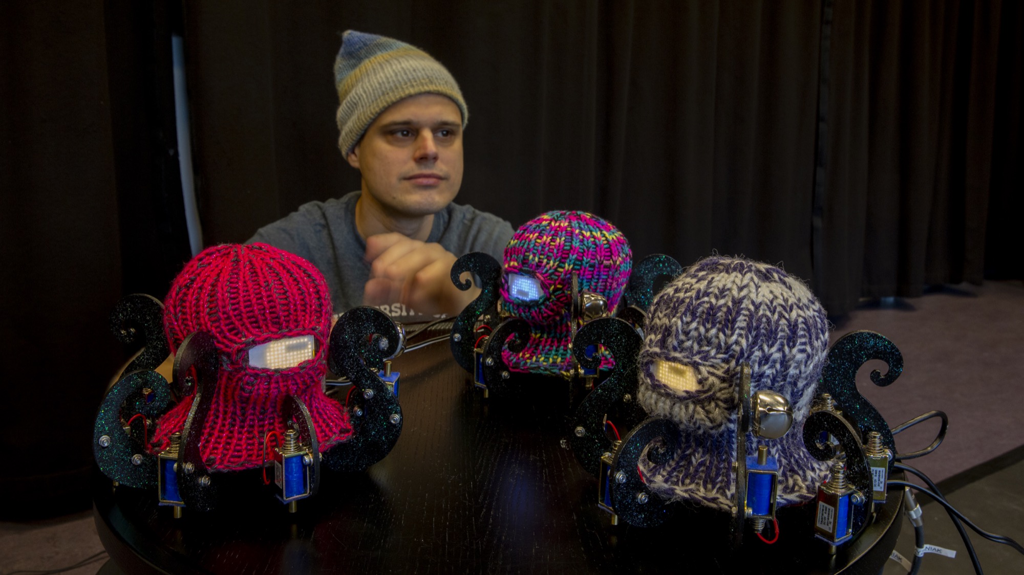 Photo Credit: Annica Thomson