Update:We now offer a Phanotom Powered version of the DIY preamp. That one was optimized for this purpose and will have slightly better performance than the one described in this article. This artilce is left here for informational purposes, but if you need a phantom powered preamp, just get the new one intead of building this circuit yourself.
Several people have asked me recently if the Marshmallow DIY contact mic preamp can be powered by +48V Phantom Power. The simple answer is that yes, it can be, but it requires a few extra components that are not already on the board. In this tutorial, I will explain what components are needed and how to use them so that Marshmallow DIY can be powered by Phantom Power.
Update
I now sell a Phantom Powered DIY board that does not require any external components. I'm leaving this post here for educational purposes, but it should no longer be necessary to build this circuit yourself.
What is phantom power?
Phantom Power is a means of supplying voltage to microphones. Microphone cables normally have three conductors. One conductor is a shield that wraps around the outside of the cable and is connected to ground. The other two conductors are twisted together in the center of the cable, and carry the audio signal. When Phantom Power is used, the mixer or audio device that the mic is plugged in to applies +48V to the two inner conductors, relative to the shield. The microphone sends the audio signal down these same conductors, causing the voltage to swing a small amount above and below +48V. The mixer or audio interface can then remove the 48V to recover the original audio signal.
How can a microphone use phantom power?
The question is how a microphone should separate the DC component (+48V) from the AC component (the audio signal) The 48V needs to go from the mixer into the microphone, and the audio signal needs to go out of the microphone into the mixer, so how should they be separated so they can be handled separately?
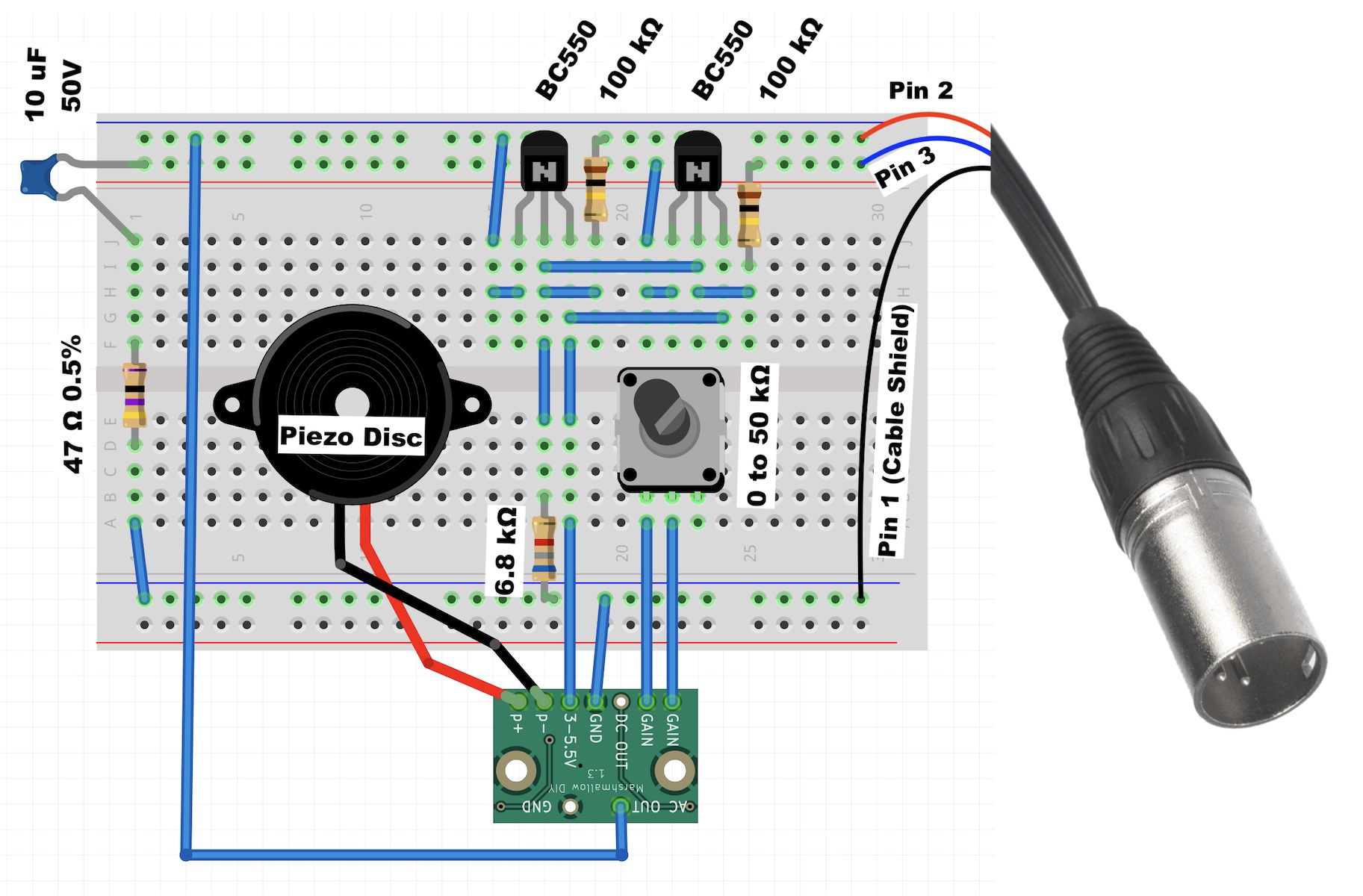
There are several ways of doing it, and here I will try to give the minimal solution. The answer is to use NPN transistors in an emitter-follower configuration on each of the inner conductors. Transistors in this configuration have high input impedance so the audio signal will not flow through them and will instead flow back to the audio device. However, the transistors can draw as much DC current as they need so the +48V will flow through them and can be used to power the microphone. The circuit for doing this is show in Figure 1.
Figure 1: Circuit diagram showing how to power Marshmallow DIY with +48V Phantom Power.
The operation of this circuit is a follows.
The outer shield of the mic cable is connected directly to the GND pin of the Marshmallow DIY. The shield should be soldered to Pin 1 on the XLR connector.
Marshmallow DIY's AC-coupled output is connected to one of the inner conductors of the audio cable; this is the conductor that is soldered to pin 2 of the XLR connector. This connection sends audio from the microphone back to the mixer.
The other inner conductor of the audio cable, the one connected to Pin 3 on the XLR connector, is connected through a 10uF capacitor and 47Ohm resistor to ground. This mimics the effect of sending another audio signal down this conductor. In this case, however, no audio is being sent, just silence, since these components are just connected to ground. The resistor and capacitor serve to balance the the signal. Balancing means that this (Pin 3) conductor will have the same output impedance as the other (Pin 2) conductor, since the Marshmallow DIY also sends its audio out through a builtin 10uF capacitor and 47 Ohm resistor. This impedance balancing helps the cable reject electromagnetic interference that it might pick up along its length. The balancing works the best when the impedances are very closely matched, so I recommend using parts with the tightest available tolerances, for example a 0.5% tolerance resistor. The capacitor should be 50V tolerant. Note that sometimes (for example when using other microphones) the Pin 3 conductor carries the inverse of the signal on Pin 2. This is referred to as a 'differential' audio signal. That could be done here too, but it would require more components, and this is the minimal example. So the output here is balanced but not differential.
There is a 100kOhm resistor and BC550 transistor connected to each of the +48V lines. Each resistor+transistor is in an emitter-follower configuration. These suck the 48V DC off of the mic cable and regulate it down to a usable voltage. The 100kOhm resistors serve 2 purposes. First, since they have very high resistance, they block the audio signal so it is not diverted down into this part of the circuit. Second, they form a voltage divider with the 6.8kOhm resistor. This voltage divider holds the base of the transistors at around 4.85V. About 0.6V is lost in the transistors, so the transistors each output around 4.25V. The outputs of the transistors are tied together and used to supply voltage to the Marshmallow DIY.
Actually Making It
I actually built the described circuit. An sketch of the circuit is shown at the top of this article. In practice, the circuit can be assembled with fewer wires than is show there, so a photograph of the circuit is show in Figure 2.
Figure 2: Photograph of the completed circuit. An illustration of this circuit is also shown at the top of this article.
A few notes:
In my circuit I used a jumper wire instead of a potentiometer, which gives the microphone a gain of 1. This is described in more detail on the Marshmallow DIY Page.
You must use the AC coupled output, not the DC coupled output. Using the DC coupled output will damage the circuit board.
The wire connecting MM DIY to ground is hidden in the image, but it is there under the board.
Overvoltage Protection
When I designed Marshmallow DIY, I anticipated that some people would want to use it in this way. Therefore it is designed with this in mind, and has the following features.
The AC-coupling capacitor is rated for 50V, so connecting it to Phantom Power will not damage it.
The voltage-input pin is filtered with an bypass capacitor that helps hold the voltage steady, so no external filtering is required.
The AC-coupled output has transient and over-voltage protection. This makes it safe to hot-plug the microphone into live 48V. It is not recommended to do this, but doing it is not likely to damage the board. This is described in more detail in a previous blog post.
Noise Performance
The noise performance of this circuit is very good. It is only a few dB higher than Metal Marshmallow Pro for the same gain setting. This is shown in Figure 3.
Figure 3: Noise Floor comparison between Metal Marshmallow Pro and Marshmallow DIY.
In any event, Metal Marshmallow Pro has a considerably fancier way of keeping the noise low, So being only 3dB higher with minimal components is very good.
Conclusion
That is how you make a DIY Phantom-Powered contact microphone with a builtin preamp. Happy music making!